Random State Array (2025)
Random State Array prototype
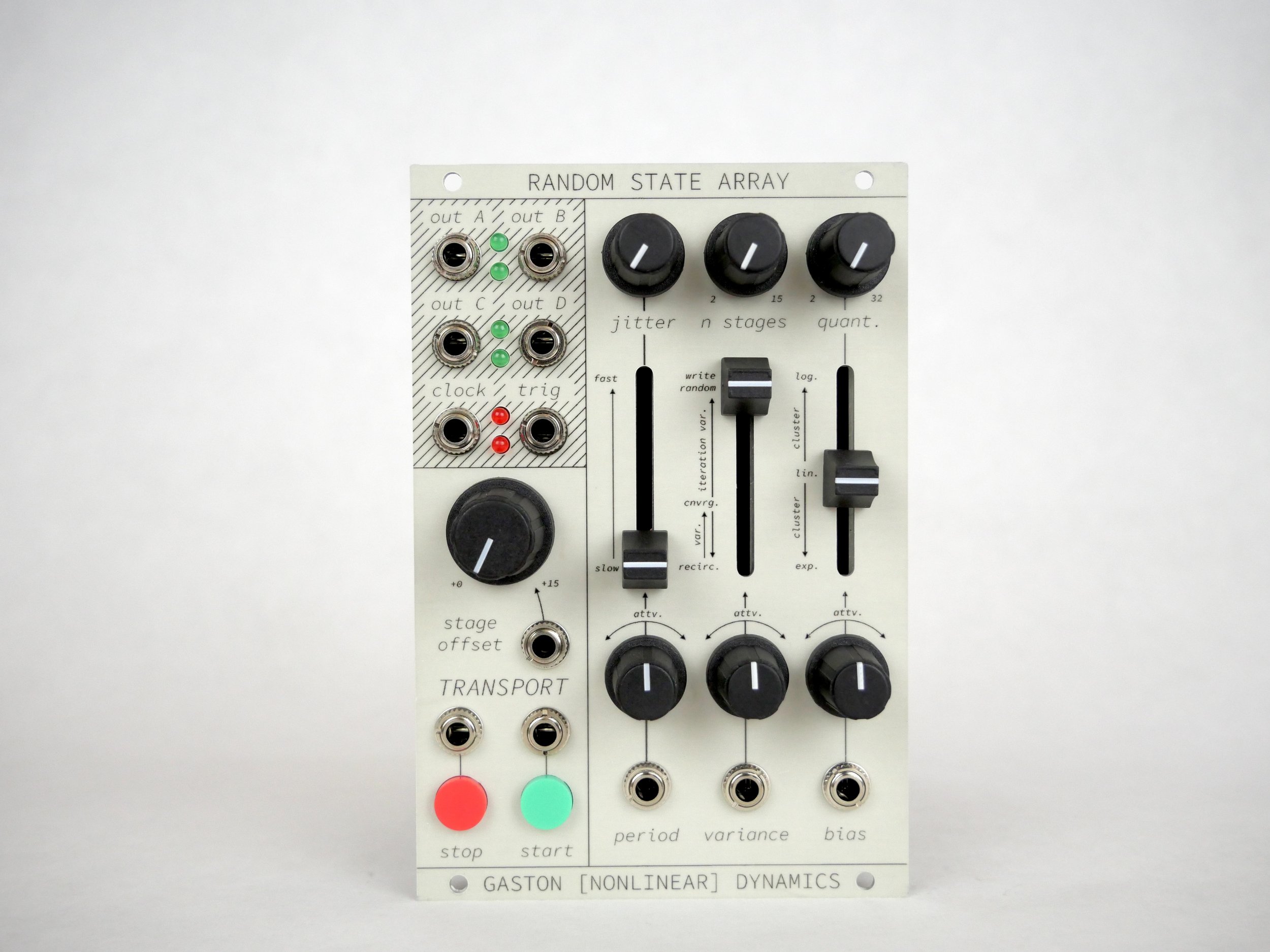
Random State Array is a stochastic control voltage utility for the [Nonlinear] Dynamics system. It may be used as a control voltage generator, or as a nonlinear voltage processor, random amplitude quantizer/range remapper, timing signal generator, and more.
Random State Array was conceptualized in collaboration with performer/composer Sarah Belle Reid. At the time of its inception in late 2024, I had already implemented multiple other random voltage generation structures—each of which felt, to me, to be too derivative of the work of prior designers. I went to Sarah—who was already acquainted with several in-progress prototypes for my instrument—and asked what she would want from a random voltage generator.
Coincidentally, she had recently acquired a Torso Electronics S-4 sampler. She showed me its modulation section—which features a “random LFO” which can be locked to a repeating (random) shape, or can incrementally (or drastically) change with each repetition of the total shape. We talked about various ways a similar structure could be implemented, and ultimately arrived at the basic idea for Random State Array—which was the first success among my many attempts to make a stochastic voltage generator for the system.
It was later pointed out to me by Vincent Edwards—who designed the cases for the systems—that Random State Array bears many conceptual similarities to Émilie Gillet’s module, Marbles. Gillet is certainly a remarkable figure, to whom I and others in the electronic musical instrument community owe a debt of gratitude—however, I cannot say that Marbles was an influence on Random State Array’s design. Alas, it would seem that there may be nothing new under the sun.
Functional Explanation
Random State Array may be conceptualized as containing a 15 x 4 array of randomly-generated values. The four-position “Y” dimension corresponds directly to the four output channels. These outputs “read” values from the array, always sharing the same “X” position as one another. The X position may be changed in two ways: by using an internal “clock” to step sequentially through the “stages,” or by using the stage offset control and CV input to address the array arbitrarily.

The internal clock generator may be engaged or disengaged using the Transport controls labeled Start and Stop, each of which assume the logical function typically associated with their names. Both Stop and Start offer both tactile switches for manual activation, as well as complementary signal inputs for remotely triggering the Stop and Start behaviors. These inputs may be addressed from any control signal, however, it is advisable to use signals with hard rising edges (such as descending ramps or triggers) for predictable/synchronous timing operations. Note that the module may be “clocked” from external sources by patching a timing source into the Stop input; when the internal clock generator is disengaged, successive timing signals sent to the Stop input will cause the Random State Array to advance to the next logical array position, much in the manner of a typical step sequencer.
The clock generator’s rate is managed via the Period slider and associated control voltage input + attenuverter. The Jitter control, located above the Period control, introduces per-stage randomization to the Period, resulting in irregular rhythmic patterns. Note that the current address value of the D row is the same signal used to determine the Jitter amount. The clock itself is represented as a stream of momentary triggers at the Clock output; the Trigger output produces random triggers according to the settings of the various other panel controls. When addressing the module using the Stage Offset control or CV input, the clock output briefly goes high each time the current stage is switched.
Every time that a stage is accessed, its contents are immediately overwritten. The Variance control determines the source of the data that is written into the array. At the uppermost end of the Variance control, new data is sourced from a free-running internal noise source, which is carefully shaped in order to ensure an optimal probability distribution across its full range of values. At the bottom end of the Variance control, new data is sourced from the stage itself—effectively overwriting the stage’s value with its most recent value. Intermediate Variance values will introduce various sorts of data recirculation by combining the stage’s most recent value with a newly-calculated random value. Different ranges of the Variance control exhibit various types of convergence/divergence. In common use, one may choose to set Variance to a high value in order to fill the array with random values, and then set Variance to its minimum value to “lock in” a sequence of randomly-generated values. Likewise, one could use the Variance control voltage input to periodically introduce randomness to an otherwise stable sequence of values—or to periodically stabilize an otherwise random sequence of values.

The n Stages control is used to determine the number of stages in the “sequence” associated with the clock generator. The lowest n value is two; the highest is 15. When set to two, if the user engages the internal clock or advances the module via triggers sent to the Stop input, the module’s outputs will each alternate between two adjacent values in the array. Setting n to 15 will result in all positions of the array being used to generate the “sequence.” Interesting results can be had by setting n fairly low and setting Variance to a moderate value—essentially producing interleaved “drunkard’s walks.” Note that the n Stages control, clock, and Stage Offset controls work in concert to determine the starting point, range, and current position from which the outputs read values. It can be interesting, for instance, to dial in a relatively short “sequence,” and to use the Stage Offset parameter as a performative control for switching the sequence start position.
Outgoing values may be quantized using the Quantization control (labeled “quant.” on the panel). Quantization does not imply adherence to a musical scale; it simply determines the number of potential values the outputs can produce. The minimum number of quantization values is two; the maximum is 32. Note that values written to the array are full-range and continuous; but values are always subjected to the quantization process before being produced at the module’s outputs. Changes to the Quantization control are only enacted upon switching stages.
Vincent Edwards—who, again, designed and built the cases for the system—suggested that it could be useful to expand the functionality of the Quantization control. Originally, the Quantization control generated a value of 2 when fully counterclockwise, and 32 when fully clockwise; this range of functionality has since been compressed to the “right” half of the knob’s rotation. However, when turning the knob counterclockwise from center, the same range of quantization values is available, with a linear slew applied to the outputs. The slew time corresponds to the current Period value (taking into account the Period slider, CV input + attenuverter, and Jitter control). The net effect is that, when using the module’s internal clock, the outputs produce continuously fluctuating random voltages. When clocking externally, the Period control affects the duration of and end-of-chain slew, whose rate is otherwise independent of the timing of incoming timing signals. Likewise, when using the Stage Offset control or CV input, the slew time is independent of the timing of stage switching.
The Bias control and associated control voltage input + attenuverter can be used to impress a variable curve shape onto the array’s values, ultimately acting as a sort of continuously variable probability distribution control. The Bias parameter is non-destructive—that is to say, it manages a process that impacts the values that are read from the array, but does not impact values written to the array. The Biasing process occurs before Quantization, so the outgoing values will always respect the conditions established by the Quantization control. Unlike the Quantization control, the Bias control is updated continuously—it is not necessary to switch stages before changes to Bias take effect. Some interesting and unusual results may occur by modulating the Bias amount continuously.
Random State Array is a concept/prototype developed primarily for personal use and is not available for sale.